Welcome to Wuhan Yoha Solar Technology Co., Ltd!
common problem
Site Map
Language:
 Chinese
 English
Welcome to Wuhan Yoha Solar Technology Co., Ltd!
common problem
Site Map
Language:
Chinese
English
| Brand: | YOHA Solar |
| Model: | YHEL-2400 |
| Unit: | unit |
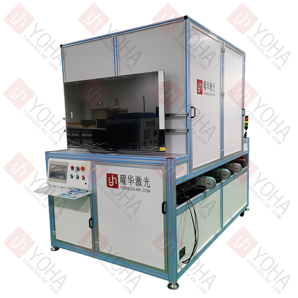
The Top-Down Imaging Solar Module EL Defect Detector is an automated optical inspection device based on the principle of electroluminescence (EL) and designed with a top-down imaging structure. It non-invasively and efficiently captures faint near-infrared light images emitted by the internal cells of photovoltaic modules after applying electrical current. This enables precise identification of various internal defects that affect module performance and reliability, such as micro-cracks, broken cells, broken fingers, black cores, black spots, sintering defects, process contamination, and PID degradation.
Core Function: Non-Destructive Internal Defect Detection
The device utilizes the Electroluminescence (EL) principle. In a darkroom environment, it passes current through the solar module, causing the cells to emit near-infrared light.
A high-sensitivity camera captures this luminescent image, visually revealing microscopic internal cell defects such as micro-cracks, broken fingers, black cores, black spots, broken cells, sintering patterns, process contamination, and low-efficiency cells. These defects are difficult or impossible to detect with the naked eye or conventional inspection methods.
Key Feature: Top-Down Imaging Design
Unlike traditional methods requiring module flipping or cameras shooting from below, "Top-Down Imaging" means the high-resolution camera is positioned directly above the module under test.
The module is typically placed horizontally or slightly tilted on the inspection platform, with the camera capturing images from above. This design simplifies the operation process, reduces module handling and flipping, lowers breakage risk, and facilitates easier integration into automated production lines.
High Precision & Automated Integration
Equipped with a high-resolution infrared camera and precision optical lenses to ensure clear images capable of identifying subtle defects.
Typically integrated with a precision motion platform (e.g., XY-axis or robotic arm) for automatic module positioning and scanning.
Includes a stabilized power supply for precise control of the current magnitude and direction (forward bias for EL imaging) injected into the module.
Built-in image processing software automatically analyzes EL images, identifying, classifying, and marking defects, and generating inspection reports.
Core Value: Enhancing Quality & Efficiency
Ensures Module Quality: Performs rigorous screening during production (e.g., pre/post-lamination) or before shipment, preventing defective modules from reaching the market and ensuring product performance and long-term reliability.
Optimizes Production Processes: Through defect statistical analysis, traces problem sources to guide improvements in cell manufacturing, soldering, lamination, and other process stages.
Improves Production Efficiency: Automated inspection is fast, reduces reliance on manual labor, meets high-speed production line requirements, and lowers overall inspection costs.
| Item | Specification |
|---|---|
| Model | YHEL-S2400 |
| Applicable Process | Defect detection for pre/post-lamination modules |
| Test Type | Mono-crystalline, Poly-crystalline cell modules |
| Camera Type | YOHA dedicated camera |
| Resolution | EL: 24 Megapixel / 60 Megapixel |
| Imaging Mode | Single/Multi-camera mode |
| Sensitivity | Detects cracks with width less than 0.03mm |
| Effective Test Area | 2600*1500mm |
| Stabilized Power Supply | 60V/20A |
| Image Capture Time | 1~60s (Adjustable) |
| Power Supply | 220V/50HZ |
| Device Dimensions | 2900×1940×1155mm |
1. Production Line Quality Control: Used for online or offline inspection on PV module production lines. Performs full or sampling inspection after module completion, quickly identifying internal defects such as cell micro-cracks, broken cells, broken fingers, poor soldering, black cores, black edges, and process contamination, ensuring outgoing module quality meets standards.
2. Laboratory R&D & Process Optimization: Used in R&D laboratories to evaluate the impact of new materials, new processes, and new structures (e.g., novel cell technologies, different soldering methods, different encapsulation materials) on module reliability and performance. Comparative analysis of EL images provides key evidence for process improvements and product design optimization.
3. Pre-Installation Power Plant Acceptance Inspection: Performs sampling or full inspection of modules delivered to the site before PV power plant installation. Identifies damage like micro-cracks or breakage caused during transportation or handling, verifies module power and quality compliance with contractual requirements, ensures foundational power plant quality, and prevents inferior components from being installed.
4. Power Plant O&M & Fault Diagnosis: Used for periodic inspections or fault localization in operational PV power plants. EL detection can reveal defects arising during operation such as hot spots, PID degradation, micro-crack propagation, solder aging, and diode failure, precisely locating problematic modules to guide maintenance and replacement, thereby improving power plant generation efficiency, safety, and lifespan.
1. Strict Darkroom Environment: The inspection environment must be completely dark (e.g., darkroom or sealed inspection chamber). Any external light source (including red lights) will interfere with EL imaging. Regularly check the darkroom door seal to prevent light leaks that increase image noise.
2. Module Placement Standardization: The module under test must lie completely flat on the inspection platform. Suspension or tilting will cause blurred images and edge distortion. The module surface must be clean and unobstructed (e.g., dust, foreign objects) to avoid misinterpretation as defects.
3. Safety Protection Measures: Module Electrification Risk: EL detection requires applying voltage (typically 40~60V) to the module. Operators must wear insulated gloves, and equipment grounding must be reliable. Mechanical Protection: For automatic transmission models, prohibit limbs from entering moving parts areas (e.g., rollers, robotic arms) during operation.
4. Optical System Maintenance: Clean the camera lens and infrared filter regularly (using professional lint-free cloth and cleaner). Fingerprints or dust will reduce imaging clarity.
5. Parameter Adaptation & Calibration: Adjust current/voltage parameters dynamically based on module type (mono/poly/thin-film) and power. Excessive voltage may damage cells; insufficient voltage fails to excite luminescence. Regularly calibrate the device using a standard calibration board to ensure defect identification accuracy (e.g., micro-crack size measurement error ≤ 0.03mm).
6. Ambient Temperature & Humidity Control: Recommended operating temperature: 10~30°C. Excessive temperature may cause device overheating shutdown; low temperature affects camera sensitivity. Maintain humidity between 30%~70% to prevent condensation on the lens or electrical short circuits. Avoid collisions with the camera mount to prevent lens focal shift affecting imaging precision.
TOP
18086473422
MESSAGE