Welcome to Wuhan Yoha Solar Technology Co., Ltd!
common problem
Site Map
Language:
 Chinese
 English
Welcome to Wuhan Yoha Solar Technology Co., Ltd!
common problem
Site Map
Language:
Chinese
English
| Brand: | YOHA Solar |
| Model: | YHMT-AAA |
| Unit: | unit |
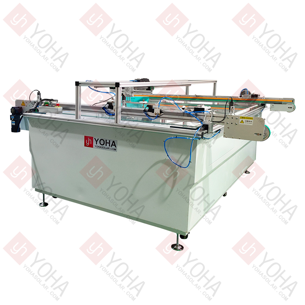
The Automatic Solar Module IV Tester is an advanced device integrating a precision electronic load, high-speed data acquisition, a xenon pulsed simulated light source (or LED array simulated light source), and an automated control system. It can accurately and non-contactly capture the current-voltage (IV) characteristic curve of a solar cell module under high-speed production line operation (typically within 0.5-2 seconds). Based on this, it automatically calculates, records, and determines key performance parameters (including maximum power point Pmpp, open-circuit voltage Voc, short-circuit current Isc, fill factor FF, series resistance Rs, shunt resistance Rsh, conversion efficiency η, etc.). Simultaneously, it automatically sorts modules or screens for defects according to preset standards. It is the core online inspection equipment for ensuring the outgoing quality and performance consistency of photovoltaic modules.
▶ High-Speed Automated Online Testing:
Designed specifically for high-speed production line cycles, capable of completing a full IV test on a single module in an extremely short time.
Achieves fully automatic loading/unloading, positioning, testing, and sorting, seamlessly integrated into automated production lines, significantly improving inspection efficiency and throughput without manual intervention.
▶ High-Precision, High-Repeatability Measurement:
Utilizes precision electronic loads, high-speed data acquisition cards, and stable, uniform simulated light sources to ensure accurate capture of the module's current-voltage (IV) characteristic curve within milliseconds.
Measurement of key parameters (Pmpp, Voc, Isc, FF, η, Rs, Rsh, etc.) boasts high accuracy and excellent repeatability, providing reliable basis for quality control and module binning.
▶ Multi-Function Integration & Intelligent Judgment:
Goes beyond basic IV testing to automatically calculate and record in-depth parameters such as fill factor, conversion efficiency, series/shunt resistance.
Features built-in intelligent analysis software that automatically judges module pass/fail based on preset quality standards and performs automatic binning.
▶ Ensures Quality Consistency & Reduces Costs:
As a core link in production line quality control, it ensures every outgoing module undergoes strict performance testing, effectively intercepting defective products and guaranteeing high consistency in product power and quality.
Through rapid, automated testing and sorting, significantly reduces labor costs and misjudgment rates, enhances overall production efficiency, and avoids customer claims and brand reputation damage caused by underperforming modules, ultimately lowering comprehensive quality costs.
| Item | Parameter |
|---|---|
| Model | YHMT-AAA |
| Light Source | Meets IEC60904-9:2020 Spectral Requirements (Class A) |
| Spectral Range | 300~1200nm |
| Irradiance | 1000W/㎡ (Adjustable 200~1200W/㎡) |
| Light Intensity Non-Uniformity | ≤2% (A) |
| Light Intensity Instability | ≤2% (A) |
| Test Result Consistency | ≤1% |
| Electrical Parameter Measurement Error | ≤2% |
| Single Flash Pulse Width | 10ms |
| Effective Test Area | 2600*1500mm |
| Power Supply | 220V/50HZ |
| Equipment Dimensions | 2900×1770×1065mm |
1. Production Line 100% Inspection & Binning: Performs 100% online power testing on every product during module manufacturing. Enables precise quality binning (Grade A/B/C) based on parameters like maximum power point (Pmax) and open-circuit voltage (Voc), ensuring outgoing modules meet the ±3% power tolerance requirement. Simultaneously detects welding or lamination defects in real-time through IV curve anomalies (e.g., steps, low fill factor).
2. Laboratory R&D & Certification: Used for ultimate efficiency verification of new cell technologies (HJT/perovskite, etc.) and quantitative analysis of performance degradation after reliability tests (e.g., damp heat cycling, PID aging) according to IEC 61215 standards, providing critical data support for technology iteration and product certification.
3. Power Plant Acceptance & O&M: Samples and tests the power of incoming modules during power plant construction (avoiding over 10% power overstatement risks). During operation and maintenance, locates faults like hot spots and diode failures by identifying abnormal IV curves (multi-peak/slope mutation) combined with infrared thermography. Periodically assesses whether the annual average degradation rate of modules exceeds the 0.8% safety threshold.
4. Decommissioned Module Recycling Assessment: Rapidly detects the residual power generation capacity of second-hand modules (70%~85% of initial power). Screens refurbishable modules to prevent PID-degraded products from entering the market. Guides the reuse of high-power modules as whole units and the disassembly and recycling of silicon/silver paste from low-power modules, maximizing resource value.
1. Strictly Adhere to Light Source Safety Protocols: The device emits high-energy, extremely bright light pulses. NEVER look directly at the light source or open the test chamber door during operation.
2. Ensure Proper Grounding & Electrical Isolation: The device involves high voltage and large current output. Reliable grounding and adherence to power supply specifications are mandatory. Regularly inspect cable insulation.
3. Precisely Control Test Environment Temperature & Humidity: Module performance is significantly affected by temperature. Pre-heat/pre-cool modules adequately to the set temperature (typically 25°C ±1°C) before testing, and precisely monitor the module surface temperature in real-time (using calibrated contact sensors). Environmental humidity must be controlled within the specified range (typically <60% RH) to prevent condensation or high-voltage discharge risks.
4. Use Test Fixtures Correctly: Clean test fixtures regularly to prevent oxidation and avoid contact resistance that causes measurement errors or local overheating damaging the module.
5. Regularly Calibrate & Maintain Core Device Components: Light source intensity (irradiance uniformity, stability), current/voltage sensor accuracy, and temperature probes are core metrology units. Calibrate them regularly according to standards (e.g., IEC 60904 series). Also maintain optical components (clean lenses/reflectors) and mechanical motion mechanisms to ensure stable and reliable equipment status.
6. Follow Standard Operating Procedures & Parameter Settings: Input module parameters accurately (e.g., nominal power, type) before testing. Set pulse width and voltage intensity cautiously to avoid irreversible thermal damage to modules caused by excessively long/strong pulses (especially for thin or temperature-sensitive materials). Allow modules to cool sufficiently after testing before the next cycle or removal. Investigate environmental, contact, and equipment status factors when handling abnormal data; NEVER arbitrarily modify or ignore abnormal results.
TOP
18086473422
MESSAGE