Welcome to Wuhan Yoha Solar Technology Co., Ltd!
common problem
Site Map
Language:
 Chinese
 English
Welcome to Wuhan Yoha Solar Technology Co., Ltd!
common problem
Site Map
Language:
Chinese
English
| Brand: | YOHA Solar |
| Model: | YH-LED |
| Unit: | unit |
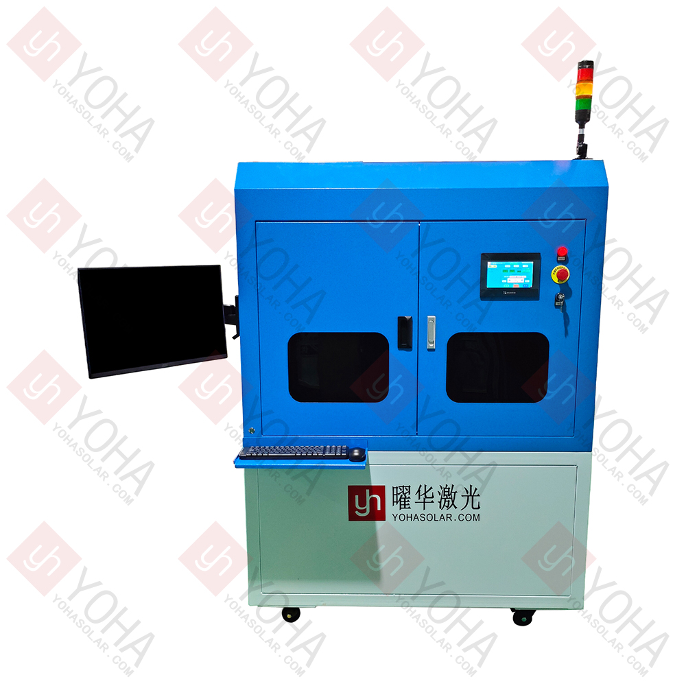
The Steady-State LED Solar Simulator for Perovskite Solar Modules is a key instrument based on an LED array light source. It provides continuous, stable solar irradiance with spectral matching compliant with international standards. Specifically designed for laboratory environments, it enables precise testing of the photoelectric performance (such as power output, efficiency, I-V characteristics, etc.) of perovskite solar cell modules.
Exceptional Spectral Match and Stability: Utilizes a precision-engineered LED array light source. Its output spectrum strictly matches the AM1.5G solar spectrum specified by international standards (e.g., IEC 60904-9), ensuring particularly high matching in wavelength bands critical to perovskite materials (e.g., the visible light region). It maintains extremely low fluctuations in spectrum and light intensity during prolonged testing (typically achieving AAA-class or higher standards), providing an accurate and reliable simulated sunlight environment for perovskite modules.
True Steady-State Output, Avoiding Transient Effects: Unlike pulsed light sources, it provides continuous, stable (non-flickering) light output, completely eliminating transient effects within perovskite modules caused by rapid light changes, such as ion migration and capacitive charging/discharging. This enables the acquisition of key performance parameters—like current-voltage characteristics (I-V curves) and maximum power point output (MPP)—that truly reflect the module's operational state under continuous sunlight conditions.
High Uniformity Illumination & Flexible Intensity Adjustment: A carefully designed optical system achieves highly uniform light intensity distribution (uniformity typically better than ±2%) across the effective irradiation area (covering typical perovskite module sizes), avoiding measurement errors from edge effects. Simultaneously, the LED light source offers wide-range, high-precision light intensity adjustment (e.g., from below 1 sun to several suns), meeting the needs for performance testing and degradation studies of perovskite modules under various irradiance conditions.
High Efficiency, Long Lifespan & Intelligent Control: The LED light source itself offers significant advantages of low energy consumption, relatively small heat generation, and ultra-long lifespan, substantially reducing operating and maintenance costs. The device integrates an advanced control system enabling real-time monitoring and automatic calibration of light intensity, spectral stability, and uniformity. It features temperature monitoring (some models offer optional temperature control platforms) and intelligent linkage with external test equipment (e.g., SourceMeters, IV testers), greatly enhancing the automation, efficiency, and repeatability of perovskite module testing.
Material Screening & Formulation Validation: Precisely simulates real sunlight environments to test the photoelectric response characteristics of different perovskite materials (e.g., pure lead, tin-lead mixed, 2D/3D structures), accelerating the development of new photoactive layer and transport layer materials.
Device Structure Optimization: Evaluates the impact of electrode design, interface engineering, and encapsulation processes on module performance through steady-state illumination tests like current-voltage (I-V) characteristics and external quantum efficiency (EQE), guiding structural innovation.
Continuous Light Soaking Tests: Provides long-duration (hundreds to thousands of hours) stable illumination, combined with temperature and humidity control modules, to simulate outdoor operating conditions. Quantifies the degradation rate and failure mechanisms (e.g., ion migration, phase separation) of perovskite modules under light and thermal stress.
Accelerated Aging Studies: Accelerates material degradation by adjusting light intensity (e.g., 1.5x suns or higher), enabling rapid validation of the reliability of encapsulation technologies and passivation strategies, shortening product lifetime certification cycles.
Production Line Performance Calibration: Conducts steady-state IV testing on modules before shipment to ensure power output, fill factor (FF), and other parameters meet specifications (e.g., IEC 61215 standard), avoiding test deviations caused by transient effects inherent to pulsed light sources.
Process Consistency Monitoring: Detects performance variations in large-area perovskite modules (e.g., 30×30 cm²) under uniform illumination, locating defects from processes like coating and laser scribing to improve yield.
International Standard Compliance Testing: Provides a steady-state illumination environment meeting the spectral match (AAA-class) and uniformity requirements of IEC 60904-9, supporting perovskite module applications for UL, TÜV, and other authoritative certifications.
Fair Performance Benchmarking: Provides a unified testing benchmark for academia and industry, eliminating efficiency overestimation issues caused by different light sources (xenon lamps, pulsed LEDs), promoting objective assessment and commercialization of perovskite technology.
Calibration Cycle: Calibrate spectral match (ensure compliance with AAA-class per IEC 60904-9) and light intensity (1000 W/m²) using a standard reference cell before first use and every 500 hours of operation (or as recommended by the manufacturer) to avoid test deviations due to LED aging.
Environmental Interference: Calibration must be performed in a darkroom at constant temperature (25±1°C) to exclude stray light and temperature fluctuations.
Forced Cooling: Perovskite modules easily heat up under continuous illumination (>50°C may accelerate degradation). Must be used with a temperature control platform (e.g., water-cooled or thermoelectric) to maintain module temperature at 25±2°C (or as specified by test protocol).
Real-time Monitoring: Integrated temperature sensors should be attached to the module backsheet; data is synchronously recorded to the test system, automatically reducing light intensity or shutting down upon temperature anomalies.
Area Matching: Irradiance uniformity (typically required >±2%) is only valid within the calibrated effective area. The module must completely cover this area during testing; edges extending beyond will cause falsely high or distorted efficiency readings.
Periodic Mapping: Scan the light spot uniformity with a multi-probe irradiance meter quarterly, especially before testing large modules (>20×20 cm²).
Four-Wire Connection: Module electrodes must use a four-wire (Kelvin) connection to the SourceMeter, separating current carrying and voltage sensing leads to eliminate voltage drop errors from lead resistance.
Grounding & Shielding: The entire system (simulator, SourceMeter, module) must share a common ground and include electromagnetic shielding to prevent high-frequency noise from the LED driver from interfering with weak current signals (nA-level dark current).
Preventing LED Aging: Avoid prolonged full-load operation (e.g., >8 hours continuous high intensity); recommend a 10-minute pause every 2 hours of operation. Regularly clean LED lens surfaces of dust (use lint-free cloth + spectroscopic-grade ethanol) to prevent light decay or spectral shift.
UV Attenuation Monitoring: If the device includes the UV LED band (300–400 nm), monitor UV output intensity every six months (perovskite is sensitive to this band) and replace UV LED modules if necessary.
Module Size Warning: Testing modules larger than the device's calibrated maximum size is strictly prohibited, as it risks damaging the optical system or causing fire.
Eye Protection: Operators must wear blue-light blocking glasses (LEDs have a high blue light component ~15%); non-test personnel should never look directly at the light source. Ensure the device housing is fully closed during operation to prevent light radiation leakage.
TOP
18086473422
MESSAGE