Welcome to Wuhan Yoha Solar Technology Co., Ltd!
common problem
Site Map
Language:
 Chinese
 English
Welcome to Wuhan Yoha Solar Technology Co., Ltd!
common problem
Site Map
Language:
Chinese
English
| Brand: | YOHA Solar |
| Model: | YHCT-ELIV |
| Unit: | unit |
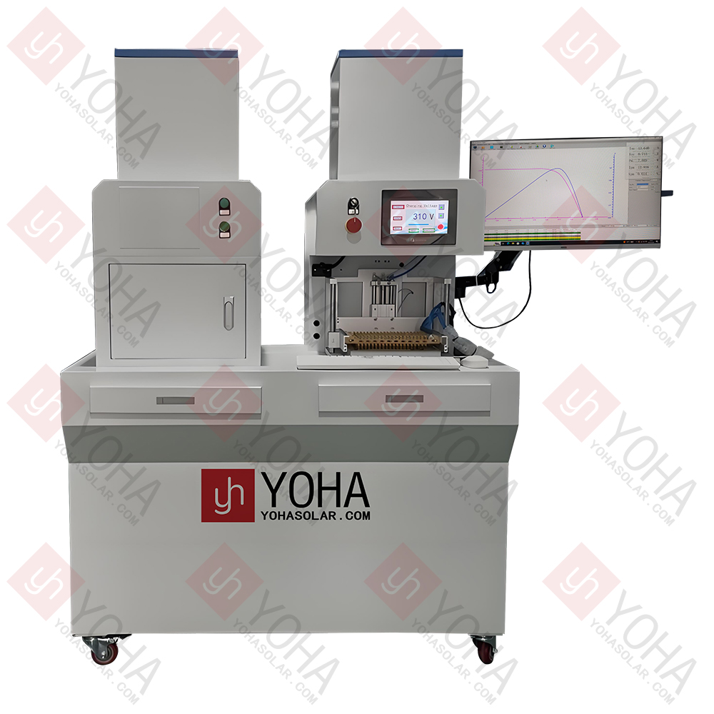
The Manual Solar Cell EL+IV Combo Tester is a benchtop device integrating Electroluminescence (EL) defect detection and Current-Voltage (IV) characteristic testing functionalities. Designed for laboratories, R&D centers, or small-batch production environments, it efficiently performs quality assessment and performance analysis on individual solar cells.
1. Integrated Functions: Performs two critical performance and quality tests on a cell in one device.
2. Manual Operation: Operators manually place the cell under test on the probe station/stage within the testing area and manually manipulate probes or pressure plates to ensure good electrical contact with the cell's electrodes.
3. IV Testing: The device applies simulated sunlight (typically via a pulsed or steady-state light source) to the cell and precisely measures its response under different voltage/current conditions, generating an I-V curve. This yields key parameters such as Open-Circuit Voltage (Voc), Short-Circuit Current (Isc), Maximum Power Point (Pmax), Fill Factor (FF), and Conversion Efficiency (η).
4. EL Testing: Under darkroom conditions (the device usually has a built-in light shield), a forward bias current is applied to the cell, causing it to emit near-infrared light. The high-sensitivity camera built into the device captures this luminescence, generating an EL image. The image clearly reveals internal defects and process issues such as micro-cracks, broken fingers, chips, black cores, black spots, sintering defects, shunt resistance, material inhomogeneity, etc.
5. Compact & Efficient: The integrated design saves space and simplifies the workflow. After testing, the device software provides both an IV parameter report and an intuitive EL defect image, facilitating rapid analysis of cell quality and performance.
| Item | Parameter |
|---|---|
| Model | YHCT-ELIV |
| Cell Specification | Can test Mono, Poly, PERC, HJT, TOPCon, etc. |
| Camera Resolution | 5 Megapixels |
| Camera Type | Custom High-Definition Industrial Camera |
| Sensitivity | Can detect cracks less than 0.03mm wide |
| Testing Direction | Vertical Downward |
| Light Source | Complies with IEC60904-9:2020 Standard |
| Irradiance | 1000W/m² |
| Irradiance Instability | ≤2% |
| Irradiance Non-uniformity | ≤2% |
| Single Flash Pulse | 100ms |
| Loading Method | Manual Loading/Unloading |
| Effective Testing Area | 230×230mm |
1. PV R&D & Process Optimization: Evaluate performance and defects of new cell materials/structures, optimize key processes (texturing, diffusion, passivation, coating, sintering, printing), and conduct failure mechanism studies.
2. PV Education & Experimentation: Provides a practical platform for universities and vocational education, visually demonstrating solar cell working principles, performance parameters, common defects, and their impact.
3. Production QC & Incoming Inspection: Serves small/medium-sized cell/module factories for sampling/full inspection of trial batches or high-value cells, defect screening and performance verification of supplier materials, and rapid troubleshooting of production line process anomalies.
4. Third-Party Testing & Certification: Provides independent, authoritative cell EL defect detection and IV performance calibration services for testing and certification bodies, used for sample analysis or dispute arbitration.
5. Module After-Sales & Failure Analysis: Locate problematic cells within failed modules, analyze the causes of their internal defects (EL) and performance degradation (IV), guiding repair or improvement.
TOP
18086473422
MESSAGE